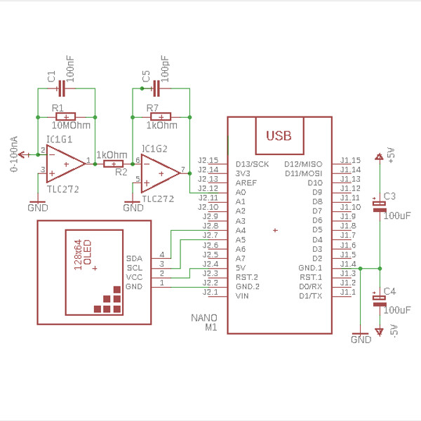
Most digital multimeters can measure a current between a few microamps and 20 amps. They usually cannot measure a current below the microamp range. There are two basic techniques for measuring low currents: the shunt technique, and the feedback ammeter technique. Here an electric scheme consisting of a very simple feedback ammeter is presented (right panel).
| | 
|
 |
The input current (100nA full scale) is connected to the inverting input of an op-amp (IC1G1, ½TLC272 LinCMOS Precision Dual
Operational-Amplifier, Input impedance: 1TΩ, Texas Instruments). The output voltage of the IC1G1 can be shown as follows: |
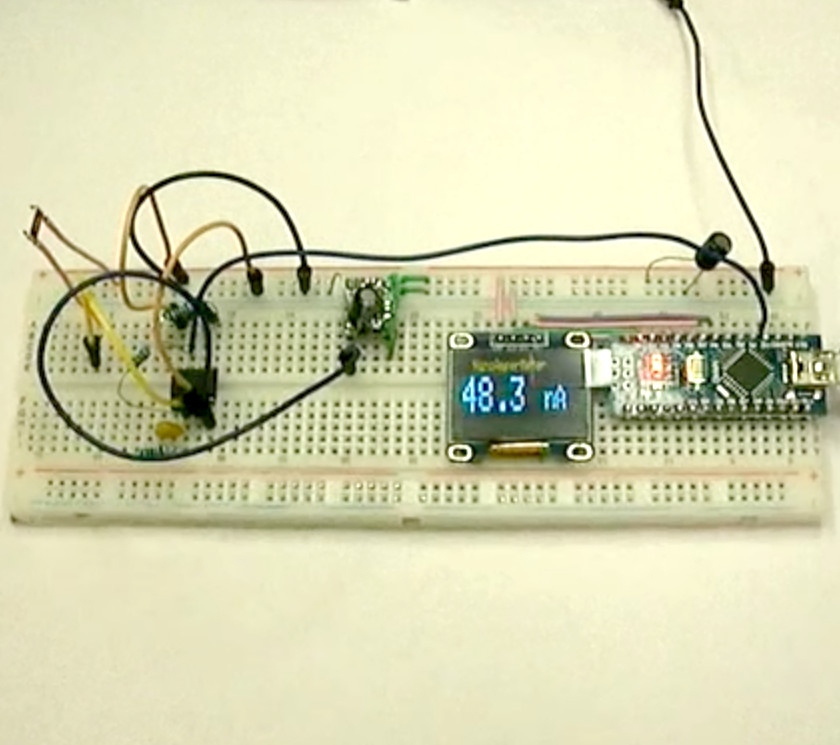
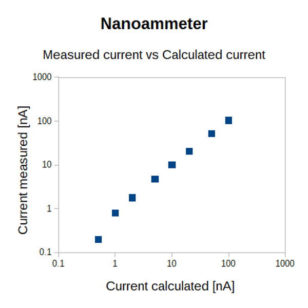
The prototype was tested using a programmable reference voltage (Electronic Explorer, Digilent) and 100MΩ/3kV/1W/5% resistors (CHV-series, Bourns). The data is presented as a table (shown below) and as a graph with a log-log scale (shown on the right panel). Additionally, a video of measurements of current flowing through a lighter flame when an external 5V voltage is applied is presented on the top of this page. 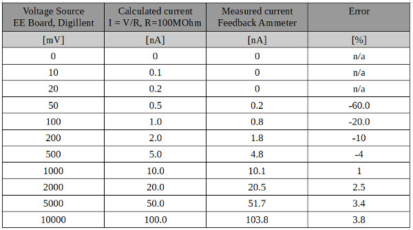
| | 
|