Trying to measure high voltages creates unusual problems, which increase with the magnitude of the voltage. The probe needs to be large to avoid flashover (the breakdown voltage of air is 30kV/cm between two spheres but it can reduce to 10kV/cm or less for sharp conductors). Additionally, the probe needs to have a very high resistance to reduce heat dissipation (a 20MΩ resistor connected to a 20kV source will dissipate 20W). A high resistance is also needed, as many high voltage power supplies can only provide a current below 1mA (sometimes 10 microamps or even less). A high voltage can be dangerous or even fatal if mishandled, so the operator needs to be sufficiently isolated from the circuit. For educational reasons this webpage presents a simple arduino based voltmeter with a range ±20kV.
| | 
|
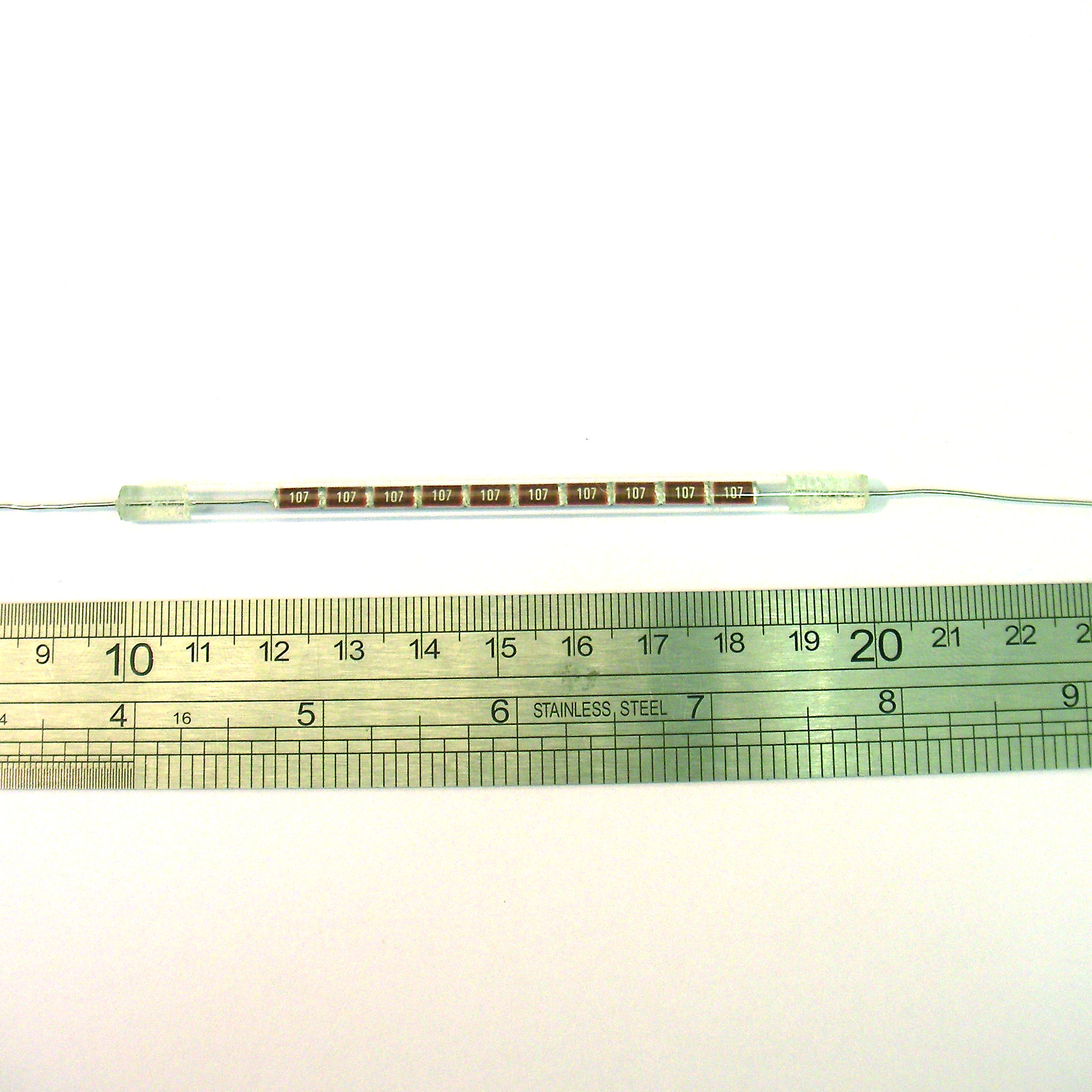 |
The input voltage is connected to a 1:10000 voltage divider (R1=1GΩ and R2=100kΩ). This design ensures that the input resistance is always 1GΩ (or 1000MΩ). R1 needs to have an unusually high resistance and also needs to have a breakdown voltage exceeding 20kV. Such resistors are rather difficult to find and expensive. An alternative solution is to solder ten 100MΩ/3kV/1W/5% resistors (Thick film high voltage chip resistor, Ruthenium glass, Temperature Coefficient ±200 PPM/°C, Voltage Coefficient of Resistance ±300 ppm/V, CHV-series 2512 [6432 Metric], Bourns) which are relatively easily available. The resistors were placed in a glass tube after being soldered. The tube was heated to around 100°C to evacuate residual water and both ends were secured with an epoxy resin. This creates a resistor of 1GΩ, 30kV, 10W with a length of 10cm (left). |
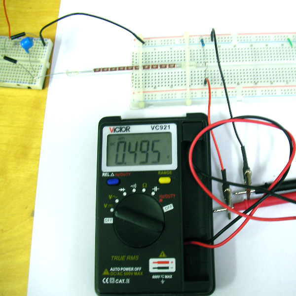
The voltage divider was tested with a 5kV source and a simple multimeter. The input voltage (5kV) connected to a 1:10000 (1GΩ:100kΩ) voltage divider resulted in a 0.5V output measured by multimeter. The circuit needs to be properly grounded for measurements.
| | 
|
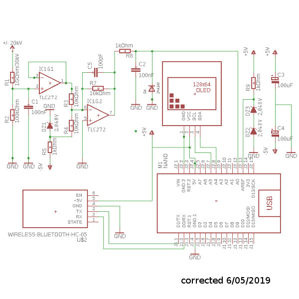 |
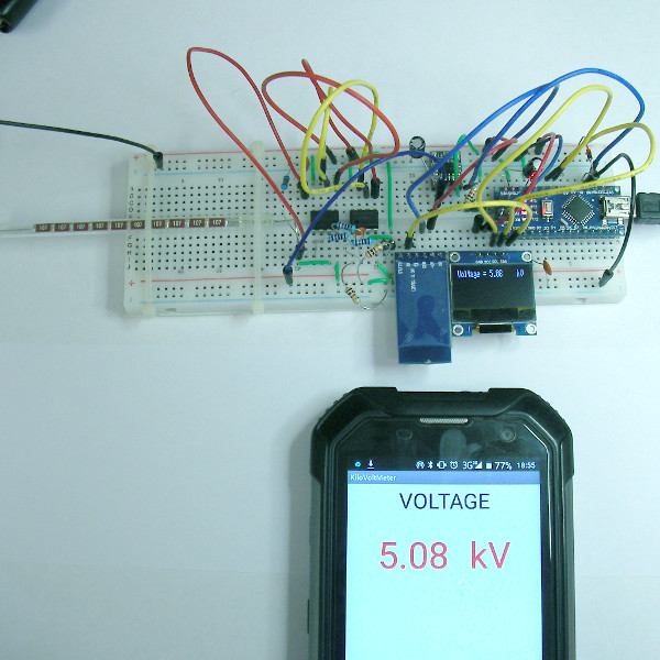
The low voltage part was built using TLC272 (LinCMOS Precision Dual Operational-Amplifier, Input impedance: 1TΩ, Texas Instruments) and an Arduino Nano (breadboard-friendly board based on the ATmega328P). For the full scale of ±20kV, the voltage divider produced ±2V output (A-test point). IC1G1 (½ TLC272) is configured as a voltage follower to separate the divider from the rest of the circuit. The output of ICG1 is ±2V (B-test point). IC1G2 (½ TLC272) is a voltage shifter (translator) in an inverting configuration. By adding -2.048V from DZ1 (LM4040-2 precision micropower shunt voltage references, 2.048V, 1%, 150 ppm/°C, Texas Instruments) and inverting the signal it produces a signal of 0-4.096V (C - test point). 0V input corresponds to 2.048V output, 20kV input corresponds to 0V output and -20kV corresponds to 4.096V. Two LM4040-2 (DZ2 and DZ3) in series create a +4.096V external ADC reference for the Arduino Nano. A negative 5V power supply for the TLC272 is created using an ICL7660 (CMOS switched-capacitor voltage converter/inverter). A 1n4148 (standard silicon switching signal diode) provides protection for the ADC from negative voltage. Data from ADC through Arduino are transmitted using an HC-05 (Bluetooth module) to any Android based device and displayed on 128x32 OLED display. The prototype was built on a breadboard (below) and an electric circuit is presented (left panel). |
 |
 |